Wiring a 3.5mm Stereo Audio Plug
This Guide is intended to show how to wire up a 3.5mm audio plug for use with most audio players.
We aim to assist with showing the most common wiring for a 3.5mm Stereo Audio plug. These plugs are commonly used with many audio output devices, as well as some of the Kitstop Audio Kits.
Resources you will need during this exercise:
- 3.5 mm Audio Plug
- Audio cable (Preferably shielded twin core for stereo audio signals).
- Soldering Iron
- Soldering Iron Stand with a damp cloth or sponge
- Diagonal Pliers (“Side-cutters”)
- Solder sucker or Solder wick (for removing unwanted solder)
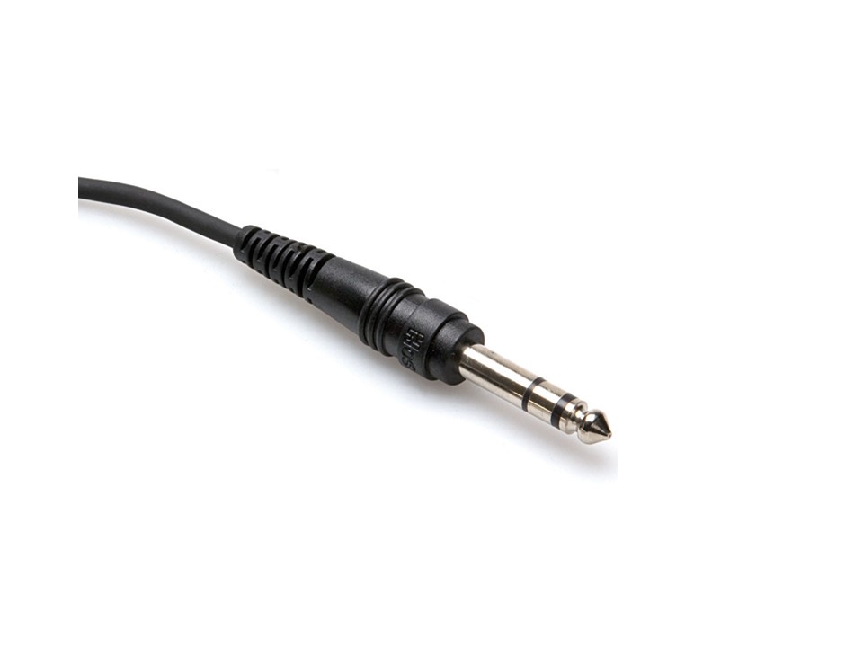
Fig 1: Finished Product (3.5mm Audio plug)
How it works:
The Plug is also often referred to as an TRS plug, where “T” = Tip, “R”= Ring, “S” = Sleeve. (Refer Fig 2) . Each part forms an insulated electrical contact which permits us to pass audio signals without them interfering with each other.
Audio equipment suppliers use a common wiring practice, which allows us to identify the most common connections. (Refer Figs 2 & 3) .
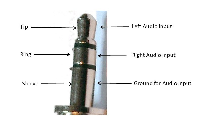
Fig 2: A close up of the plug and the different segments of it.
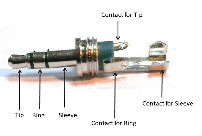
Fig 3: Identifying the different connections of an Audio plug.
Preparing the Audio Cable:
Strip and tin the Audio cable for soldering to the Plug.
Warning note:
If you are using a “Shielded” cable, try to minimize any damage to the shielding braid. Also pay particular attention to gathering all the braids of the shield together and minimize the risk of them creating a short circuit to the inner conductors. See the sequence recommended in figures 4 to 6.
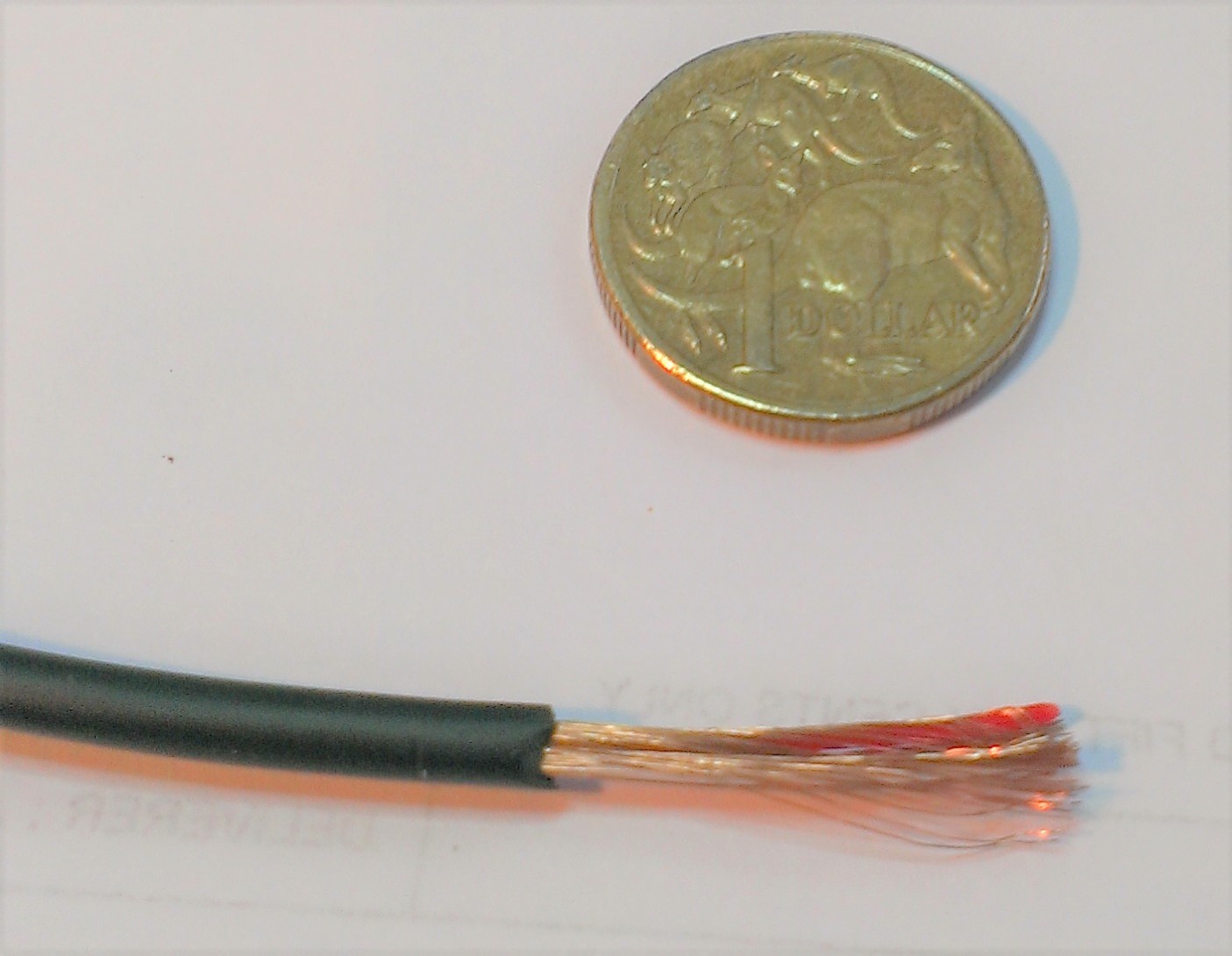
Fig 4: Audio cable with outer insulator removed.
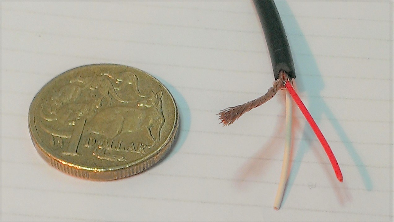
Fig 5: Audio cable with shield carefully gathered together before stripping the centre conductors.
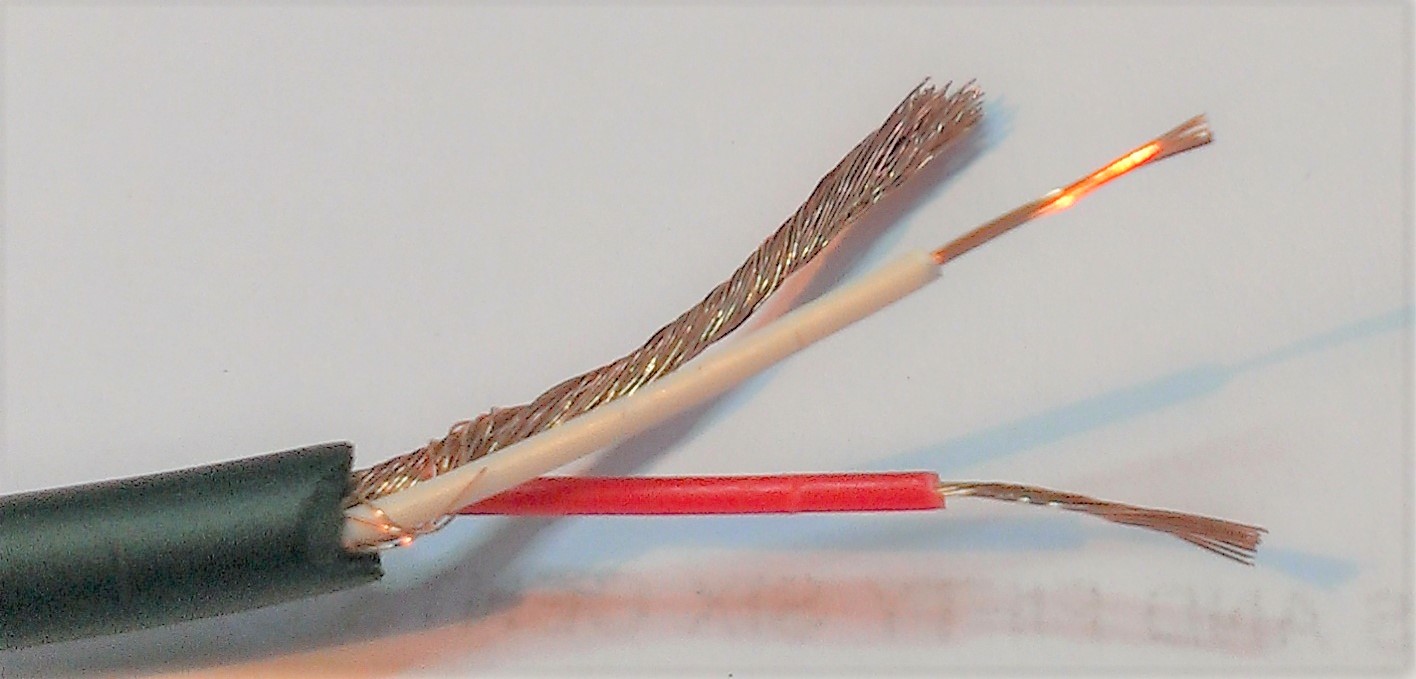
Fig 6: Audio cable with all three conductors ready for tinning.
Connecting the wires:
Warning: Slide the plug housing onto the cable before starting !
Our suggestion: For students you may like to introduce our in-house “R” connecting rule, which goes as follows:
- Connect the “R”s together to avoid confusion.
- R = Red wire
- R = Ring on the Audio plug
- R= Right speaker for stereo applications.
See figure 7 for our suggested wiring.
Some good news: This “R” rule is not mandatory… the system can still work with other wiring arrangements. It simply makes things more predictable!
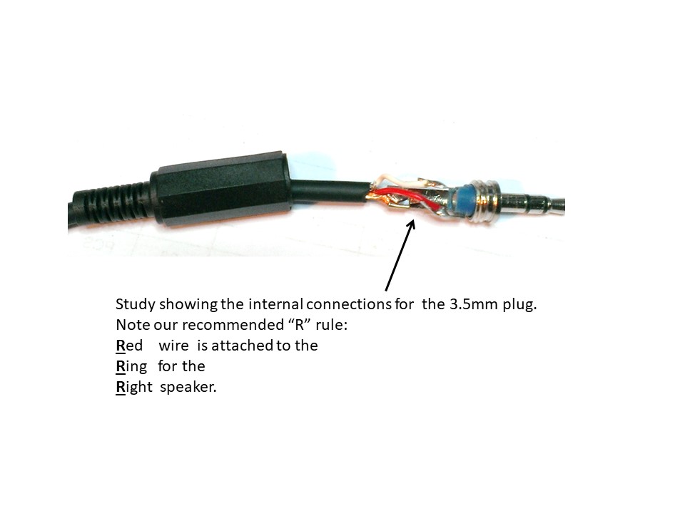
Fig 7: Showing the internal connections of the 3.5mm Audio plug prior to closing the housing.
Suggestion: How to identify the different connection points on the back of the 3.5mm audio plug:
Sleeve: Usually this is the larger (and longer) tab which is formed as part
of many plug bodies.
Tip: See Fig 8 for a close up of the solder tab. Usually the “TIP” is the
centre connection point.
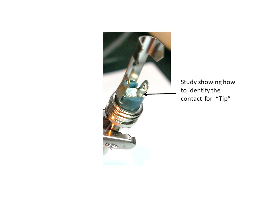
Fig 8: Identifying the internal “TIP” connection of the 3.5mm Audio.
Ring: Usually this is the last remaining connection available! Close study
will show that this connector is well insulated from all other points.
Reseat the housing:
After connecting the wires, the housing on the back of the plug should be able to screw back into position.
We often find students will have applied too much solder to the connections, and therefore may need some careful adjusting before the housing will reseat properly.
The wires available at the other end of the cable:
Shield = Ground
Red = Right input
White = Left input